
 English
 Español
 Deutsch
 日本語
日本語 Polska
 Français
 中國
中國 한국의
한국의 Українська
 Italiano
 Nederlands
 Türkçe
 Português
 Bahasa Indonesia
 Русский
 हिंदी
हिंदीlifting transfer mechanism solidworks2016 Modelo 3D


-50%

skp
tzd
Buildings


-50%

max
tzd
Environment
-50%
max sldprt x_t
tzd
Machines
-50%

skp
tzd
Buildings

HALLOWEEN
PRE SALE 50% OFF
$
4.00 USD
Você tem $0.00 Créditos. Comprar créditos

- Formatos disponíveis: SolidWorks (.sldprt) 9.37 MB
- Animados:No
- Textura:No
- Equipados:No
- Materiais:
- Low-poly:No
- Coleção:No
- Mapeamento UVW:No
- Plugins Utilizados:No
- Pronto para impressão:No
- Scan 3D:No
- Conteúdo adulto:No
- PBR:No
- Geometria:Polygonal
- UVs não embalados:Unknown
- Visualizações:2729
- Data: 2020-07-15
- ID do Item:301983
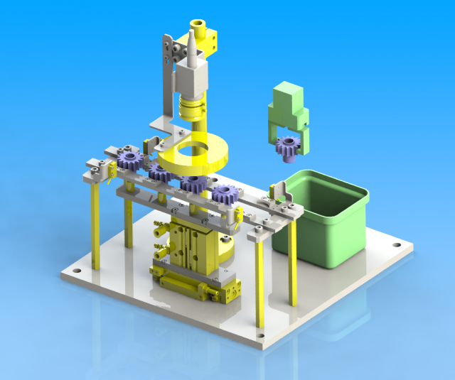
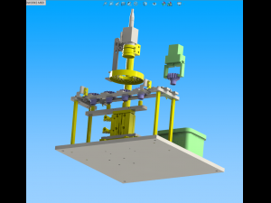
lifting transfer mechanism
specifications
purpose and action
check the pinion by image recognition.
object artifact
resin gear
workpiece specification: φ 34, height 29mm
characteristic
specification and size
overall dimension: 320 × 320 × 341mm
total height: 341 mm
up and down stroke: 30mm
feed stroke: 50mm
specification and size
workpiece feed positioning accuracy: ± 0.5
selection basis of main parts
compared with the ordinary cylinder with guide rod, its cross-sectional area is about 1 / 2, and its size is small.
key points of design
calculation process of main parts
the cylinder diameter is selected according to the workpiece load conditions, and the camera and lens are selected according to the inspection resolution.
select inner diameter of pneumatic linear sliding cylinder
service conditions: horizontal installation
condition value: load weight m = 0.5kg
friction coefficient μ = 0.2
according to the gravity acceleration g = 9.8m/s
actual load f = μ mg = 0.2 × 0.5 × 9.8 = 0.98n
service pressure p = 0.4mpa
according to the load rate η = 50%
required cylinder force f0 = (f / η) × 100 = (0.98 / 50) × 100 = 1.96n
cylinder inner diameter do = √ (1.274 × fo / p) = √ (1.274 × 1.96 / 0.4) = 2.50mm
the inner diameter of the cylinder is 12mm, no problem.
select inner diameter of cylinder with guide rod
service conditions: vertical installation
condition value: load weight m = 0.21kg
according to the gravity acceleration g = 9.8m/s
actual load f = mg = 0.21 × 9.8 = 2.06 n
service pressure p = 0.4mpa
according to the load rate η = 50%
required cylinder force f0 = (f / η) × 100 = (2.06 / 50) × 100 = 4.12n
cylinder inner diameter do = √ (1.274 × fo / p) = √ (1.274 × 4.12 / 0.4) = 3.62mm
the inner diameter of the cylinder is 12mm, no problem.
select camera, lens
condition: check object workpiece: gear profile 34mm
: inspection of unqualified products (above 0.1 mm)
camera selection: 1 / 1.8 1.92 megapixel (1600 × 1200)
1 / 1.8 ≈ 1 / 2,
field of view 42 × 56 (in accordance with workpiece shape)
wd90mm lens selection close up lens.
{0.035mm for 1 pixel (1600 pixels for 56mm)
·0.1 mm can be checked.
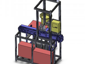
key points of structure making and design
the cylinder with guide rod and pneumatic linear slide table are used in the workpiece conveying.
when the workpiece is unstable in the image inspection position (workpiece floating, etc.), the workpiece posture recognition sensor should be added. Pronto para impressão: Não
Leia maisspecifications
purpose and action
check the pinion by image recognition.
object artifact
resin gear
workpiece specification: φ 34, height 29mm
characteristic
specification and size
overall dimension: 320 × 320 × 341mm
total height: 341 mm
up and down stroke: 30mm
feed stroke: 50mm
specification and size
workpiece feed positioning accuracy: ± 0.5
selection basis of main parts
compared with the ordinary cylinder with guide rod, its cross-sectional area is about 1 / 2, and its size is small.
key points of design
calculation process of main parts
the cylinder diameter is selected according to the workpiece load conditions, and the camera and lens are selected according to the inspection resolution.
select inner diameter of pneumatic linear sliding cylinder
service conditions: horizontal installation
condition value: load weight m = 0.5kg
friction coefficient μ = 0.2
according to the gravity acceleration g = 9.8m/s
actual load f = μ mg = 0.2 × 0.5 × 9.8 = 0.98n
service pressure p = 0.4mpa
according to the load rate η = 50%
required cylinder force f0 = (f / η) × 100 = (0.98 / 50) × 100 = 1.96n
cylinder inner diameter do = √ (1.274 × fo / p) = √ (1.274 × 1.96 / 0.4) = 2.50mm
the inner diameter of the cylinder is 12mm, no problem.
select inner diameter of cylinder with guide rod
service conditions: vertical installation
condition value: load weight m = 0.21kg
according to the gravity acceleration g = 9.8m/s
actual load f = mg = 0.21 × 9.8 = 2.06 n
service pressure p = 0.4mpa
according to the load rate η = 50%
required cylinder force f0 = (f / η) × 100 = (2.06 / 50) × 100 = 4.12n
cylinder inner diameter do = √ (1.274 × fo / p) = √ (1.274 × 4.12 / 0.4) = 3.62mm
the inner diameter of the cylinder is 12mm, no problem.
select camera, lens
condition: check object workpiece: gear profile 34mm
: inspection of unqualified products (above 0.1 mm)
camera selection: 1 / 1.8 1.92 megapixel (1600 × 1200)
1 / 1.8 ≈ 1 / 2,
field of view 42 × 56 (in accordance with workpiece shape)
wd90mm lens selection close up lens.
{0.035mm for 1 pixel (1600 pixels for 56mm)
·0.1 mm can be checked.
key points of structure making and design
the cylinder with guide rod and pneumatic linear slide table are used in the workpiece conveying.
when the workpiece is unstable in the image inspection position (workpiece floating, etc.), the workpiece posture recognition sensor should be added. Pronto para impressão: Não
Precisa de mais formatos?
Se precisar de um formato diferente, por favor abra um novo Support Ticket e solicite isso. Podemos converter modelos 3D para: .stl, .c4d, .obj, .fbx, .ma/.mb, .3ds, .3dm, .dxf/.dwg, .max. .blend, .skp, .glb. Não convertemos cenas 3D e formatos como .step, .iges, .stp, .sldprt.!
Se precisar de um formato diferente, por favor abra um novo Support Ticket e solicite isso. Podemos converter modelos 3D para: .stl, .c4d, .obj, .fbx, .ma/.mb, .3ds, .3dm, .dxf/.dwg, .max. .blend, .skp, .glb. Não convertemos cenas 3D e formatos como .step, .iges, .stp, .sldprt.!
lifting transfer mechanism solidworks2016 Modelo 3D sldprt, De tzd
lifting transferNão há comentários para este item.
-50%
surf3d
Machines
-50%
surf3d
Machines
-50%
surf3d
Machines
-50%
surf3d
Machines
-50%
surf3d
Machines
-50%
surf3d
Machines
-50%
surf3d
Machines
-50%
surf3d
Machines
-50%
surf3d
Machines
-50%
surf3d
Machines