English
 Español
 Deutsch
 日本語
日本語 Polska
 Français
 中國
中國 한국의
한국의 Українська
 Italiano
 Nederlands
 Türkçe
 Português
 Bahasa Indonesia
 Русский
 हिंदी
हिंदीlifting transfer mechanism solidworks2016 3D 모델

CYBER MONDAY
SALE 50% OFF
$
4.00 USD
- 작성자에게 제품 지원 요청

- 이용 가능한 포맷:
- 아이템 ID:301983
- 날짜: 2020-07-15
- 애니메이티드:No
- 텍스쳐드:No
- 리그드:No
- 재료:
- 로우 폴리곤:No
- 컬렉션:No
- UVW 매핑:No
- 플러그인 사용 됨:No
- 프린트 준비:No
- 3D 스캔:No
- 성인용 콘텐츠:No
- PBR:No
- 지오메트리:Polygonal
- 언래핑 된 UVs:Unknown
- 조회:2822
설명
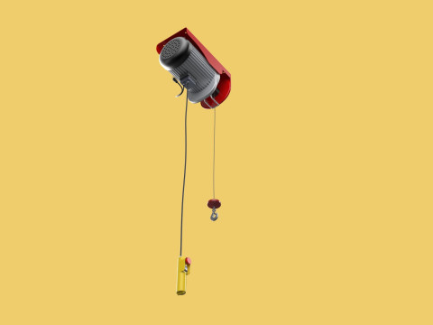
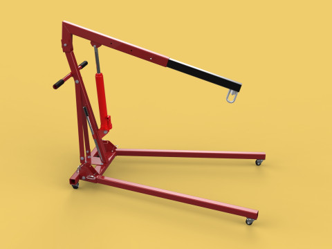
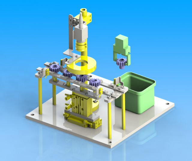
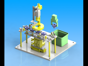
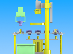
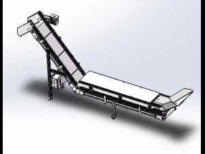
lifting transfer mechanismspecifications
purpose and action
check the pinion by image recognition.
object artifact
resin gear
workpiece specification: φ 34, height 29mm
characteristic
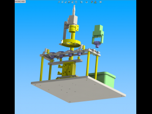
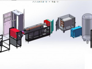
specification and size
overall dimension: 320 × 320 × 341mm
total height: 341 mm
up and down stroke: 30mm
feed stroke: 50mm
specification and size
workpiece feed positioning accuracy: ± 0.5
selection basis of main parts
compared with the ordinary cylinder with guide rod, its cross-sectional area is about 1 / 2, and its size is small.
key points of design
calculation process of main parts
the cylinder diameter is selected according to the workpiece load conditions, and the camera and lens are selected according to the inspection resolution.
select inner diameter of pneumatic linear sliding cylinder
service conditions: horizontal installation
condition value: load weight m = 0.5kg
friction coefficient μ = 0.2
according to the gravity acceleration g = 9.8m/s
actual load f = μ mg = 0.2 × 0.5 × 9.8 = 0.98n
service pressure p = 0.4mpa
according to the load rate η = 50%
required cylinder force f0 = (f / η) × 100 = (0.98 / 50) × 100 = 1.96n
cylinder inner diameter do = √ (1.274 × fo / p) = √ (1.274 × 1.96 / 0.4) = 2.50mm
the inner diameter of the cylinder is 12mm, no problem.
select inner diameter of cylinder with guide rod
service conditions: vertical installation
condition value: load weight m = 0.21kg
according to the gravity acceleration g = 9.8m/s
actual load f = mg = 0.21 × 9.8 = 2.06 n
service pressure p = 0.4mpa
according to the load rate η = 50%
required cylinder force f0 = (f / η) × 100 = (2.06 / 50) × 100 = 4.12n
cylinder inner diameter do = √ (1.274 × fo / p) = √ (1.274 × 4.12 / 0.4) = 3.62mm
the inner diameter of the cylinder is 12mm, no problem.
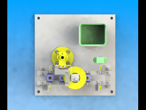
select camera, lens
condition: check object workpiece: gear profile 34mm
: inspection of unqualified products (above 0.1 mm)
camera selection: 1 / 1.8 1.92 megapixel (1600 × 1200)
1 / 1.8 ≈ 1 / 2,
field of view 42 × 56 (in accordance with workpiece shape)
wd90mm lens selection close up lens.
{0.035mm for 1 pixel (1600 pixels for 56mm)
·0.1 mm can be checked.
key points of structure making and design
the cylinder with guide rod and pneumatic linear slide table are used in the workpiece conveying.
when the workpiece is unstable in the image inspection position (workpiece floating, etc.), the workpiece posture recognition sensor should be added. 프린트 준비: 아니오
다른 포맷이 필요하세요?
다른 포맷이 필요하시면, 새로운 지원 티켓을 열어 요청하세요. 저희는 3D 모델을 다음으로 변환할 수 있습니다: .stl, .c4d, .obj, .fbx, .ma/.mb, .3ds, .3dm, .dxf/.dwg, .max. .blend, .skp, .glb. 자유 형식 변환우리는 3D 장면을 변환하지 않습니다 .step, .iges, .stp, .sldprt와 같은 형식도 포함됩니다.!
사용 정보
lifting transfer mechanism solidworks2016 - 기본 또는 확장 라이선스에 따라 이 로열티 프리 3D 모델을 개인적 및 상업적 목적으로 사용할 수 있습니다.기본 라이선스는 디지털 광고, 디자인 및 시각화 프로젝트, 비즈니스 소셜 미디어 계정, 네이티브 앱, 웹 앱, 비디오 게임, 그리고 물리적 또는 디지털 최종 제품(무료 및 유료 모두)을 포함한 대부분의 표준 사용 사례를 포괄합니다.
확장 라이선스는 기본 라이선스에 따라 부여된 모든 권리를 포함하며 사용 제한이 없으며, 로열티 프리 조건 하에 3D 모델을 상업적 프로젝트에 무제한으로 사용할 수 있습니다.
더 보기
환불이 보장되나요?
네, 환불을 보장합니다. 작품 구입 후 렌더나 설명에서 오류를 발견하시면, 저희는 최대한 빨리 해당 문제를 수정 할 것입니다. 저희가 해당 오류를 수정 할 수 없는 경우, 저희는 귀하의 주문을 취소하며 아이템 다운로드 24 시간 내에 금액을 환불해드립니다. 더 자세한 정보는 여기를 참조하세요키워드
이 저작자의 랜덤 아이템


-50%
sldprt step
tzd
Machines

이 아이템에 대한 코멘트 없음.