English
 Español
 Deutsch
 日本語
日本語 Polska
 Français
 中國
中國 한국의
한국의 Українська
 Italiano
 Nederlands
 Türkçe
 Português
 Bahasa Indonesia
 Русский
 हिंदी
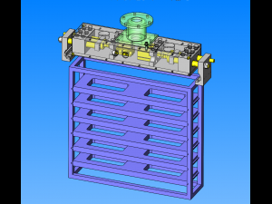
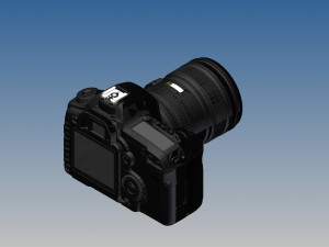
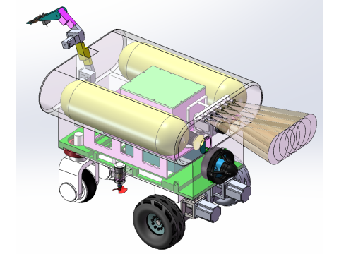
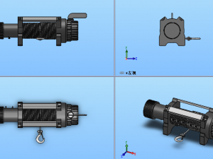
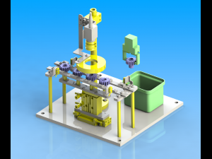
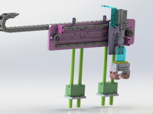
हिंदीclamping mechanism of heavy workpiece 3D Modell
-50%
tzd
Buildings
-50%
tzd
Dining Room

-50%
tzd
Buildings

SALE ENDS
$
3.00

- Verfügbare Formate: SolidWorks (.sldprt) 7.12 MB
- Animiert:No
- Texturen:No
- Rigged:No
- Materialien:
- Low-poly:No
- Sammlung:No
- UVW mapping:No
- Plugins Used:No
- Druckfertige:No
- 3D Scan:No
- Erwachsene:No
- PBR:No
- Geometrie:Polygonal
- Unwrapped UVs:Unknown
- Betrachter:2619
- Datum: 2020-07-15
- Artikel-ID:301997
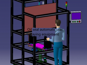
purpose and action
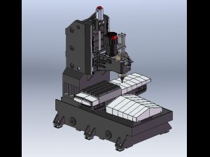
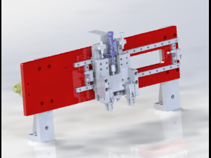
when clamping heavy-duty workpieces, the claw clamping mechanism is used instead of the large inner diameter cylinder.
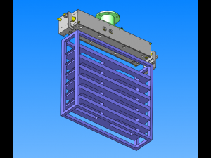
environment and operability
the device acts as a manipulator connected to the front end of the manipulator.
the air supplied by the arm drives the cylinder to open and close the manipulator.
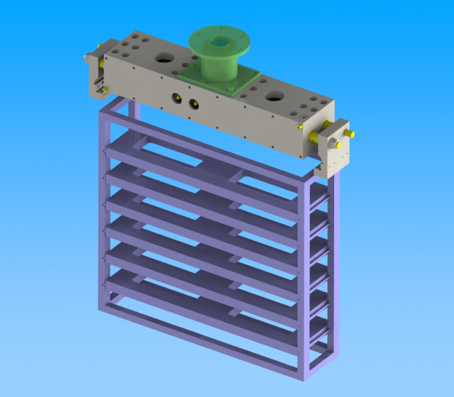
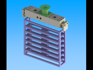
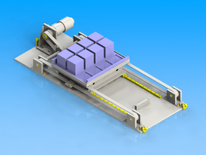
object artifact
workpiece
dimensions: w573 x d150 x h15mm
weight: 5.4kg
workpiece rack
dimensions: w153 x d600 x h102mm
weight: 15.3kg
characteristic
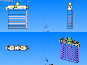
specification and size
unit as a whole
maximum dimension: w695 (with manipulator open) x d137 x h149mm
profile size: w560 x d137 x h102mm
cylinder
reference side: cylinder diameter φ 50mm, stroke 30mm
attached side: cylinder diameter φ 40mm, stroke 30mm
workpiece action
horizontal jump acceleration fixed: 0.2g
instantaneous maximum horizontal jump acceleration: 1g
accuracy and load
the inertia force at the maximum acceleration of horizontal runout is less than the retraction side thrust of cylinder.
selection basis of main parts
safe cylinder capacity for handling.
key points of design
calculation process of main parts
φ 40mm cylinder output (when horizontal runout is 1g)
inertia force of cylinder: f = ma = (m1 + m2) a
total weight of workpiece: m1 = 6 × 5.4 + 15.3 = 47.7kg
overall weight of manipulator: m2 = 2.11kg
→ f=(47.7+2.11)×9.8=488n
retraction thrust: f2 = η xa2xp
load rate: η = 1 (according to product catalogue)
retracted pressure area: a2 = 1056 mm 2 (according to product catalogue)
service pressure: p = 0.5mpa
f2=1 x 1056 x 0.5 = 528n
safety factor: f2 / f = 528 / 488 = 1.08 times
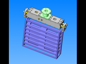
key points of structure making and design
using two guide shafts on one side, the reaction force borne by the manipulator is offset by the shear force between the guide shaft and the fixed seat, and the torque will not be transmitted to the cylinder structure.
there is a through-hole on the sliding surface of the guide shaft, so oil-free bushing is used. Druckfertige: Nein
Mehr lesenwhen clamping heavy-duty workpieces, the claw clamping mechanism is used instead of the large inner diameter cylinder.
environment and operability
the device acts as a manipulator connected to the front end of the manipulator.
the air supplied by the arm drives the cylinder to open and close the manipulator.
object artifact
workpiece
dimensions: w573 x d150 x h15mm
weight: 5.4kg
workpiece rack
dimensions: w153 x d600 x h102mm
weight: 15.3kg
characteristic
specification and size
unit as a whole
maximum dimension: w695 (with manipulator open) x d137 x h149mm
profile size: w560 x d137 x h102mm
cylinder
reference side: cylinder diameter φ 50mm, stroke 30mm
attached side: cylinder diameter φ 40mm, stroke 30mm
workpiece action
horizontal jump acceleration fixed: 0.2g
instantaneous maximum horizontal jump acceleration: 1g
accuracy and load
the inertia force at the maximum acceleration of horizontal runout is less than the retraction side thrust of cylinder.
selection basis of main parts
safe cylinder capacity for handling.
key points of design
calculation process of main parts
φ 40mm cylinder output (when horizontal runout is 1g)
inertia force of cylinder: f = ma = (m1 + m2) a
total weight of workpiece: m1 = 6 × 5.4 + 15.3 = 47.7kg
overall weight of manipulator: m2 = 2.11kg
→ f=(47.7+2.11)×9.8=488n
retraction thrust: f2 = η xa2xp
load rate: η = 1 (according to product catalogue)
retracted pressure area: a2 = 1056 mm 2 (according to product catalogue)
service pressure: p = 0.5mpa
f2=1 x 1056 x 0.5 = 528n
safety factor: f2 / f = 528 / 488 = 1.08 times
key points of structure making and design
using two guide shafts on one side, the reaction force borne by the manipulator is offset by the shear force between the guide shaft and the fixed seat, and the torque will not be transmitted to the cylinder structure.
there is a through-hole on the sliding surface of the guide shaft, so oil-free bushing is used. Druckfertige: Nein
Sie brauchen mehr Formate?
Falls Sie ein anderes Format benötigen, eröffnen Sie bitte ein neues Support-Ticket und fragen Sie danach. Wir können 3D Modelle in folgende Formate konvertieren: .stl, .c4d, .obj, .fbx, .ma/.mb, .3ds, .3dm, .dxf/.dwg, .max. .blend, .skp, .glb. Wir konvertieren keine 3D Szenen und Formate wie .step, .iges, .stp, .sldprt usw!
Falls Sie ein anderes Format benötigen, eröffnen Sie bitte ein neues Support-Ticket und fragen Sie danach. Wir können 3D Modelle in folgende Formate konvertieren: .stl, .c4d, .obj, .fbx, .ma/.mb, .3ds, .3dm, .dxf/.dwg, .max. .blend, .skp, .glb. Wir konvertieren keine 3D Szenen und Formate wie .step, .iges, .stp, .sldprt usw!
clamping mechanism of heavy workpiece 3D Modell sldprt, Von tzd
clamping mechanism heavy workpieceEs gibt keine Kommentare zu diesem Artikel.
-50%
iam skp sldprt 3dm blend lwo max stl obj
surf3d
Machines
$10.38
$20.77
-50%
surf3d
Machines
-50%
surf3d
Machines