English
 Español
 Deutsch
 日本語
日本語 Polska
 Français
 한국의
한국의 Українська
 Italiano
 Nederlands
 Türkçe
 Português
 Bahasa Indonesia
 Русский
 中國
中國 हिंदी
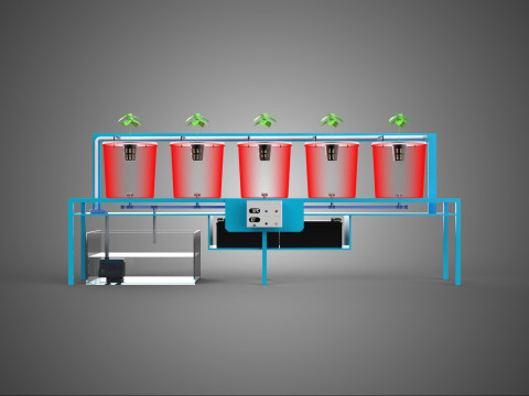
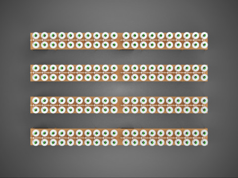
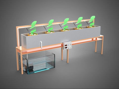
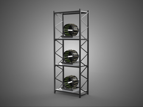
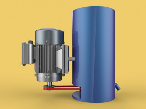
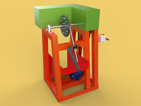
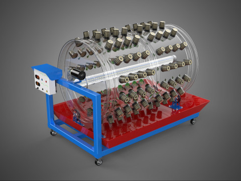
हिंदीPARABOLIC ANTENNA TRACKER TRACKING SYSTEM 3D Model
$
4.95 USD
- Request product support by the author

- Available formats:
- Item ID:503318
- Date: 2024-04-17
- Polygons:21,022
- Vertices:17,330
- Animated:No
- Textured:No
- Rigged:No
- Materials:
- Low-poly:No
- Collection:No
- UVW mapping:No
- Plugins Used:No
- Print Ready:No
- 3D Scan:No
- Adult content:No
- PBR:No
- AI Training:No
- Geometry:Poly NURBS
- Unwrapped UVs:Unknown
- Views:2093
Description
The model contains the most popular formats:1. 3DS MAX: *.max
2. Blender: *.blend
3. Rhinoceros: *.3dm
4. SketchUp: *.skp
5. Wavefront OBJ: *.obj *.mtl (Multi Format)
6. FBX: *.fbx (Multi Format)
7. STEP: *.step *.stp (NURBS)
8. IGES: *.iges *.igs (NURBS)
9. ACIS: *.sat (NURBS)
10. 3DS MAX all ver.: *.3ds (Multi Format)
11. Stereolithography: *.stl
12. AutoCAD: *.dwg
- Each file was checked for opening and full content by the model.
- The 3D model was created on real base. It’s created accurately, in real units of measurement, qualitatively and maximally close to the original.
- Renders Are made in Luxion Keyshot
- “WE PROVIDE 3D MODEL CHEAP PRICE BUT WITH GOOD QUALITY”
- If you need any other formats we are more than happy to make them for you. Contact me for any question :)
Sincerely Your, SURF3D
MORE INFORMATION ABOUT 3D MODELS :
An antenna tracking system tracks a primary antenna to follow a moving signal source, such as a communication satellite. A secondary antenna has a greater beam width than the primary antenna and receives the same tracking signal from the satellite. The primary antenna is tracked according to a predetermined search pattern which causes a variation in the signal amplitude depending upon the relative location of the satellite and the antenna position. The signal strength signals from the two antennas are input to a summation function which takes the difference of the two signals. The noise and signal variation component of the two signals is substantially the same and is therefore eliminated from the resulting difference signal. An antenna control unit utilizes the resulting difference signal to select the optimum signal strength for the particular step of the search pattern. This system is particularly applicable to extremely high frequency communication channels (86 GHz and above) which are subject to atmospheric distortion and noise. Antenna Tracking Systems can apply to Broadband and Microwave Radio Systems as well for Point-to-Point and Point-to-Multipoint communications Print Ready: No
Need more formats?
If you need a different format, please send us a Conversion Request. We can convert 3D models to: .stl, .c4d, .obj, .fbx, .ma/.mb, .3ds, .3dm, .dxf/.dwg, .max. .blend, .skp, .glb. Free Format ConversionWe do not convert 3d scenes and solid formats such as .step, .iges, .stp, .sldprt etc!
Usage Information
PARABOLIC ANTENNA TRACKER TRACKING SYSTEM - You can use this royalty-free 3D model for both personal and commercial purposes in accordance with the Basic or Extended License.The Basic License covers most standard use cases, including digital advertisements, design and visualization projects, business social media accounts, native apps, web apps, video games, and physical or digital end products (both free and sold).
The Extended License includes all rights granted under the Basic License, with no usage limitations, and allows the 3D model to be used in unlimited commercial projects under Royalty-Free terms.
Read more
Do you provide Money Back Guarantee?
Yes, we do. If you purchased a product and found some error in the renders or description, we'll try to fix the problem as soon as possible. If we cannot correct the error, we will cancel your order and you will get your money back within 24 hours from downloading the item. Read more conditions hereKeywords
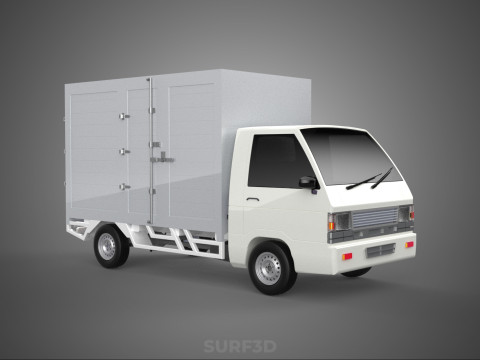
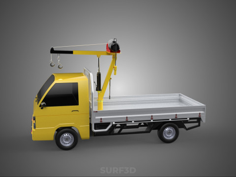
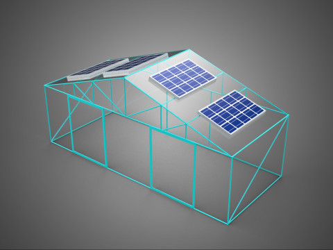
Random Items from the author
Display all items added by surf3d-50%
3dm max skp sat fbx step blend dwg iges
surf3d
Machines

-50%

surf3d
Beverage
-50%

3ds 3dm blend dae dwg fbx iges ipt lwo
surf3d
Lamp
$5.50
$11.00
-50%
surf3d
Trailers
-50%
surf3d
Truck
-50%
surf3d
Machines
-50%
surf3d
Tools
There are no comments for this item.
-50%
surf3d
Tools
-50%
surf3d
Tools
-50%
surf3d
Tools
-50%

surf3d
Tools
-50%
surf3d
Tools